Vortex Studio 2017b Feature – Grade Quality Sensor
Authorcmlabs
Published
2017-09-26
Despite being considered as heavy equipment, a motor grader requires very precise manipulation of the blade to achieve good leveling or trenching.
Because of this, we need a method to verify the quality of the work done by the grader.
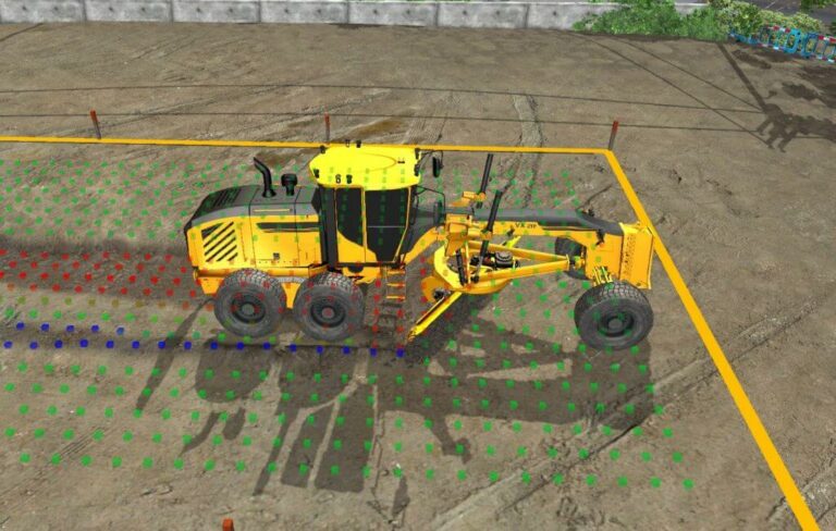
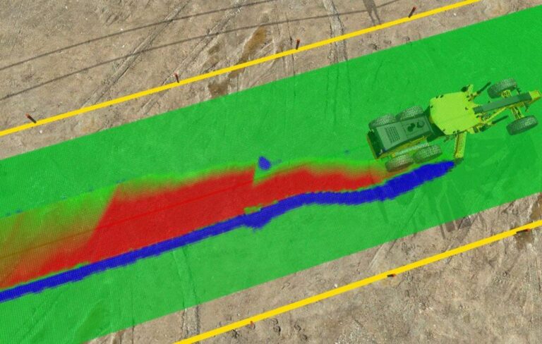
The Grade Quality Sensor in action
Vortex Studio’s new Grade Quality Sensor extension allows you to quantify the quality of the work. You can add a Grade Quality Sensor to a scene, mechanism or terrain. To do so, select “Earthwork Systems” from the Toolbox and double-click “Grade Quality Sensor.” When a Grade Quality Sensor is added to a mechanism, its bounding box is of default size (1,1,1) and centred at the origin.
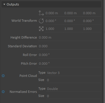
Sensor outputs
This can be changed with the help of the resize manipulator and the translation or orientation manipulator:
Resize and orientation manipulators.
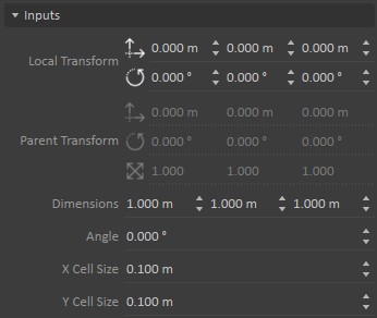
This can be also be done via updating the Local Transform and setting the dimensions in the Properties panel:
Properties panel
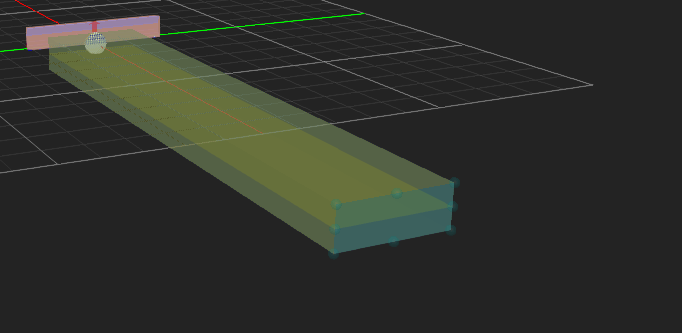
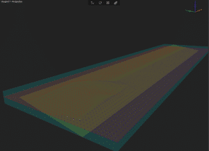
After positioning the box inside the area where the sampling of the soil will be taken, it’s time to orient the reference plane. This plane can be considered as the “goal”: the machinery should change the shape of the soil to be as close as possible in position and orientation to this reference plane. The reference plane is always in the middle of the box and has no rotation by default. Its position can be adjusted by moving the box with the help of the translation manipulator or by changing the dimensions of the box. The orientation of the reference plane will follow the orientation of the box, but it can also be changed independently by changing the Angle value in the sensor’s Dynamics Properties panel. The plane is drawn as a yellow plane inside the box:
A reference plane at 37°
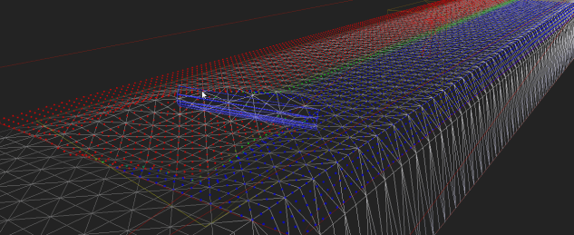
In order to compute the quality of the graded soil surface, a least squares plane is computed from a set of sample points taken from the soil surface. The computed plane is the “best fit plane” for the sample point cloud and is used to quantify the error of the grade. To find the sample points, the box of the Grade Quality Sensor is discretized by increments of the provided cell size (see the inputs “X Cell Size” and “Y Cell Size” of the sensor’s Dynamics Properties panel) along the local X- and Y-axes on the Z=0 plane of the Grade Quality Sensor. Then those points are projected onto the soil surface, thus forming the sample points used for the least squares plane computation.
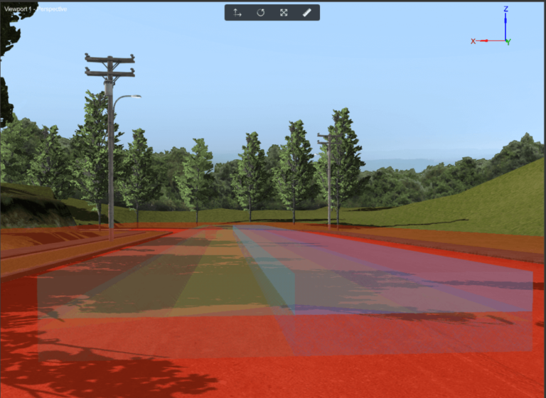
Graphics of the Grade Quality Sensor displaying visual cues for the quality of the grade, with the colour gradient
Least square plane (in red) created from the intersection points at an angle
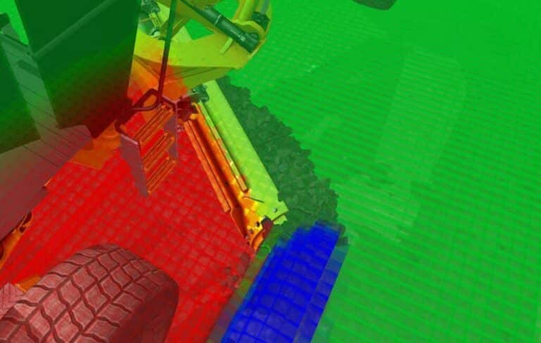
Grade Quality Sensor in action
The distance between the center of the reference plane and the center of the least square plane is available as the output “Height Difference” in the sensor’s Dynamics Properties panel, and also the “Angle Difference” in rotation around the local X-axis (roll) and Y-axis (pitch) of the box, between the reference plane and the least square plane. The height’s Standard Deviation is also given as an output since it is possible for a motor grader to have the blade at a right angle but still create waves in the soil.
Waves in the soil
If the Visible field is selected in the sensor’s Graphics Properties panel, small boxes will be displayed at the sample points on the soil surface. By default: – If the points are blue, the sample point is above the reference plane. – If the points are red, the sample point is below the reference plane. – If the points are green, the sample point is on the reference plane. There’s a gradient of colors in between; it can be user-defined by specifying the Gradient Start Color, Gradient Middle Color, and Gradient End Color in the sensor’s Graphics Properties panel. The size of the displayed boxes can be specified by setting the Point Size parameter in the sensor’s Graphics Properties panel. The work done by a motor grader is complex since it might be needed to create a V-shaped ditch, or to level a terrain/road with different slopes. Luckily, it is possible to have multiple Grade Quality Sensors in a scene or mechanism, and each one is independent. So, to obtain a complex shape, just place multiple Grade Quality Sensors side by side. The quality of the work done by the grader can then be calculated as a sum of the error outputs of all the sensor. In the following scene, two Quality Grade Sensors are put side by side to create the required shape.